|
Box2D Joint Toy
Game Physics with a 2D Physics Engine
|
|
Box2D Joint Toy
Game Physics with a 2D Physics Engine
|
The Box2D Joint Toy demonstrates some important Box2D joints, including revolute, gear, prismatic, wheel, distance, and pulley joints. It is divided into 7 levels. This code demo has no sound. The remainder of this page is divided into six sections. Section 2 lists the controls and their corresponding actions, Section 3 tells you how to build it, Section 4 gives you a list of actions to take in the game to see some of its important features, Section 5 gives a breakdown of the code, important features, Section 6 contains some programming problems, and Section 7 addresses the question "what next?".
| Help (this document) | |
| Toggle draw mode from "sprites only", to "sprites and lines", to "lines only" | |
| Reset current level | |
| Advance to next level | |
| Do an interesting thing (see Section 4.1 to Section 4.7) | |
| Save screenshot to a file | |
| Quit game and close the window |
This code uses SAGE and Box2D. Make sure that you have followed the SAGE Installation Instructions and the Box2D Installation Instructions. Navigate to the folder 8. Box2D Joint Toy in your copy of the sage-physics repository. Run checkenv.bat to verify that you have set the environment variables correctly. Open Box2D Joint Toy.sln with Visual Studio and build the Release configuration. Alternatively, run Build.bat to build both Release and Debug configurations.
This toy has 7 levels. As mentioned in Section 2, the Enter key advances to the next level and the Backspace key resets the current level to the initial conditions. The levels are as follows: the windmill (Section 4.1), round and square gears (Section 4.2), nautilus gears (Section 4.3), rack-and-pinion (Section 4.4), car and bridge (Section 4.5), Newton's cradle (Section 4.6), and elephant drop (Section 4.7). In every level the Space bar does an interesting things. These are described more detail in the subsections below.
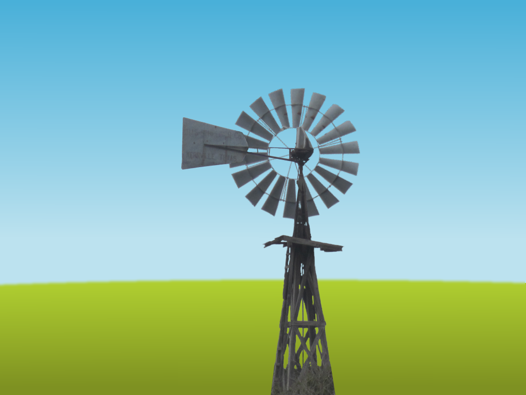
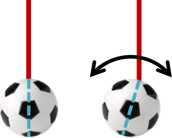
A windmill with a revolute joint connecting the fan to the body. The revolute joint has a motor (see Fig. 1). The Space bar reverses the motor's direction of rotation. Notice that the fan takes a while to spin up to full speed, and when the direction of the motor is reversed they slowly spin down to zero before spinning up in the opposite direction. This is a property of motors in Box2D and will depend of the mass of the body being rotated.
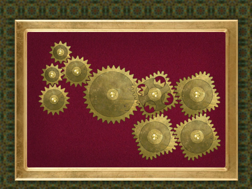
A system of 9 interlocked gears constructed using revolute and gear joints (see Fig. 2). The largest gear has a motor and the others are driven by their gear joints. The Space bar reverses the motor's direction of rotation. Notice that the gears take a while to spin up to full speed, and when the direction of the motor is reversed they slowly spin down to zero before spinning up in the opposite direction. Notice also how the teeth of the gears appear to mesh. However, if you look closely you will see that they do not mesh exactly. This is because we are not computing the physics of the teeth, we are simply rotating the gears at the right speeds assuming that the sprites are drawn with teeth that mesh correctly. The 4 square gears mesh perfectly the same way that round gears do. They are cheating in a way - they require no extra code over and above what is necessary for ordinary round gears.
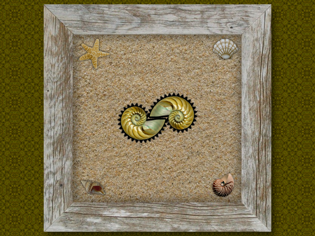
A pair of nautilus gears, which are gears in the shape of a nautilus shell (see Fig. 3). The left gear has a revolute joint with a motor. The right gear has variable speed, so they cannot be animated by Box2D. We have to animate it ourselves which means doing a little math, which we will cover in Section 5.3. The Space bar reverses the motor's direction of rotation. Notice that the gears take a while to spin up to full speed, and when the direction of the motor is reversed they slowly spin down to zero before spinning up in the opposite direction.
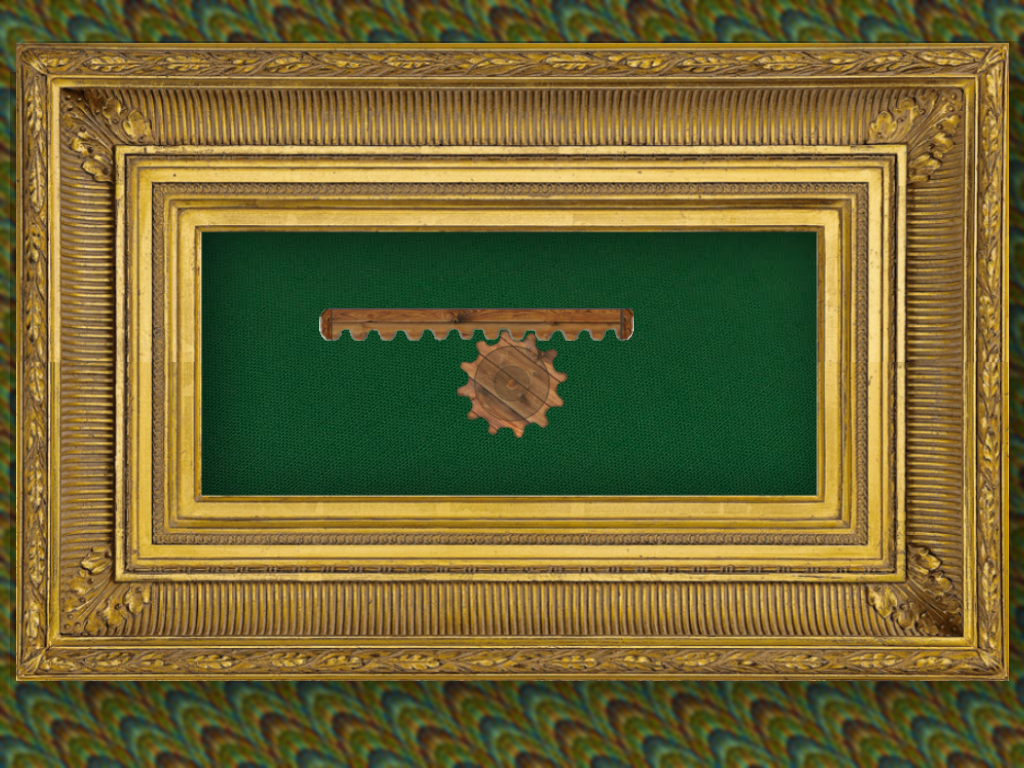
A rack-and-pinion consists of a round gear called a pinion connected to a toothed rod called a rack (see Fig. 4). When the pinion rotates, the rack moves horizontally. The pinion has a revolute joint with a motor. The rack is connected to the pinion using a gear joint and a prismatic joint. The Space bar reverses the motor's direction of rotation. Notice that the pinion takes a while to spin up to full speed, and when the direction of the motor is reversed it slowly spins down to zero before spinning up in the opposite direction. Also notice the sudden stop when the pinion reaches its extreme left and right positions.
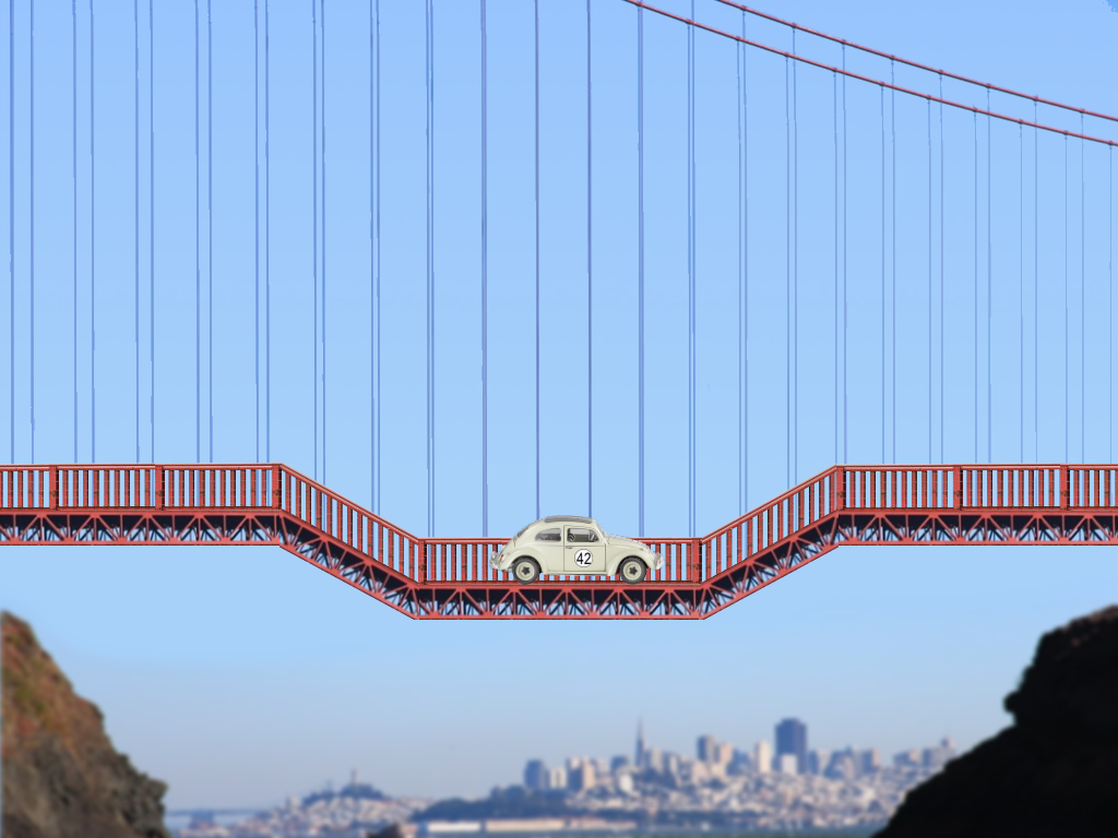
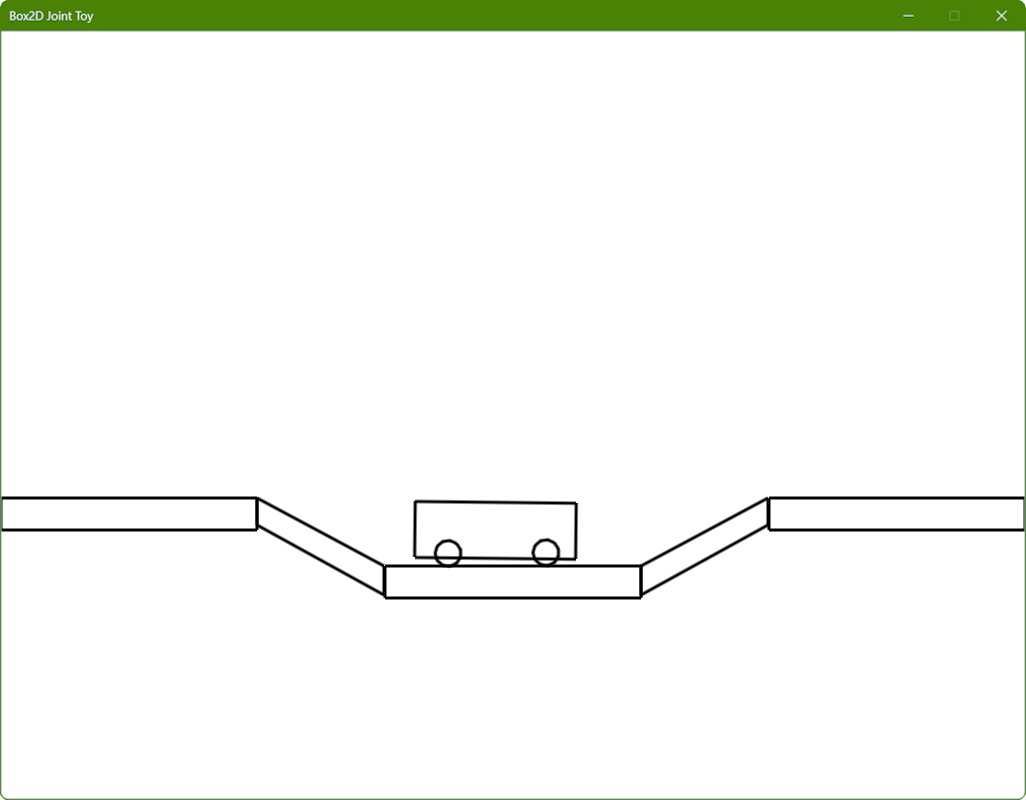
A car drives autonomously back and forth over a pair of ramps (see Fig. 5). The car is constructed using a pair of wheel joints that have motors. The Space bar reverses the motors' directions of rotation. Notice that the car takes a while to get to full speed, and when the direction of the motors is reversed it slows down to zero before speeding up in the opposite direction. Also notice the suspension that makes the car bounce when it goes over the ramps. If you are fast with the Space bar you may be able to get the car stuck. If you do, reset it with the Backspace key.
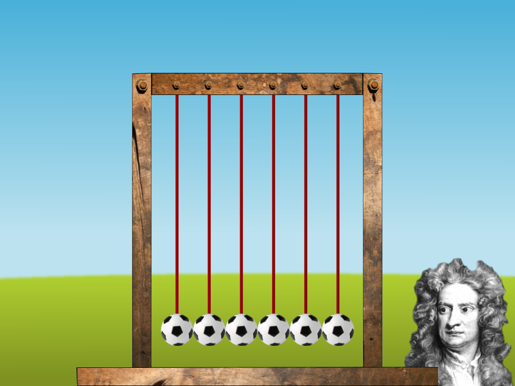
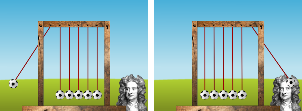
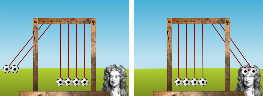
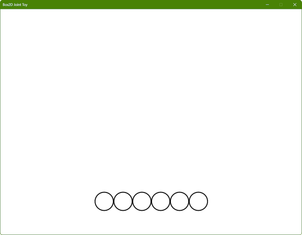
Distance joints are used to construct a 2D Newton's Cradle with 6 balls (see Fig. 6). When the balls are stopped, hitting the Space bar will lift and release from 1 to 5 balls in sequence. After that it should behave like a real Newton's Cradle. Fig. 7 shows a screen shot with one ball raised (left), and the result after the collision (right). Fig. 8 shows a screen shot with two balls raised (left), and the result after the collision (right). When the balls are in motion, the Space bar stops them.
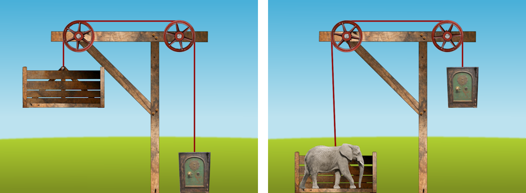
A pulley joint is used to lift a safe when an elephant is dropped into a wooden cradle (see Fig. 9). The pulley wheels and ropes are animated in code. When the elephant is not present, the Space bar makes it drop in from above. When the elephant is present, the Space bar makes it disappear. You can make the elephant appear and disappear at any point in the cradle's travel, not just when it is at the top or bottom. Notice that in Fig. 9 (right) the cradle is not immediately below the left rim of the pulley wheel above so that the rope from the pulley to the cradle is not vertical, whereas that portion of the rope is perfectly vertical in Fig. 9 (left). This is because the elephant is not dropped exactly above the center of the cradle, causing it to rock from side to side as it falls.
Each of the levels has its own class, each of which is derived from CLevel. CLevel contains code and data that will be used by most of the levels. Some of its functions are stubs. A pointer to a class representing the current level is maintained in CCommon::m_pLevel, which is of type CLevel*. Many of CLevel's member functions are virtual so that they can be overridden in any particular level class if desired. Most importantly, CLevel has an std::vector of pointers to CObject for you to store your objects, and function CLevel::Draw to draw the objects in in (although of course this may be overridden in derived classes), a function stub CLevel::Action to perform the "interesting action" in response to the space bar (see Section 2), and a function stub CLevel::Move that will be used in Section 5.3, Section 5.4, and Section 5.5 to implement things that are not supported in Box2D. CLevel::Move or a function derivde from it will be called from CGame::ProcessFrame once per animation frame.
The most interesting portions of the code for each of the level classes is described in the following subsections: the windmill (Section 5.1), round and square gears (Section 5.2), nautilus gears (Section 5.3), rack-and-pinion (Section 5.4), car and bridge (Section 5.5), and Newton's cradle (Section 5.6), and elephant drop (Section 5.7).
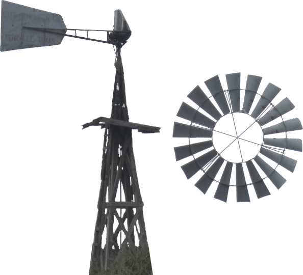
The windmill level is implemented in class CWindmill, which is derived from CLevel. The CWindmill constructor calls CWindmill::CreateFan to create an instance of CObject for the fan, which is drawn using the sprite shown in Figure 10 (right); and calls CWindmill::CreateBase to create an instance of CObject for the base, which is drawn using the sprite shown in Figure 10 (left).
CObject has a pointer to a Box2D body CObject::m_pBody of type b2Body*. CWindmill::CreateFan declares a body definition bd and sets its type and position fields. It then declares an instance of b2CircleShape called s and sets its radius to half the width of the sprite in Figure 10 (right), translated from Render World to Physics World coordinates. It then declares a fixture definition fd and sets its shape to s and its density somewhat arbitrarily to 0.1f. It then creates a Physics World body for the fan by calling
m_pPhysicsWorld->CreateBody(&bd)
and saving the pointer to the Box2D body returned in a local variable pBody. The instance of CObject for the fan is then created by calling
new CObject(eSprite::WindmillFan, pBody)
and pushing the pointer returned at the back of the inherited object list CLevel::m_stdObject. Finally, the fixture for the shape is attached to the body by calling
pBody->CreateFixture(&fd);
although this could be called before the instance of CObject was created.
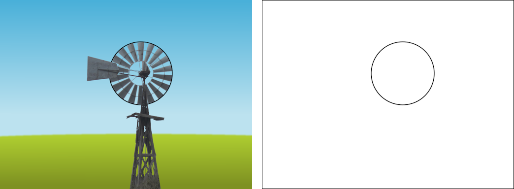
CWindmill::CreateBase, on the other hand, creates an instance of CObject with a pointer to a Box2D body that does not have a fixture attached to it. This results in the sprite for the windmill base being drawn as in Fig. 11 (left), but it does not participate in Box2D collision detection and response and is not drawn when only Box2D bodies are drawn as in Fig. 11 (right). As far as Box2D is concerned, then, the world consists of two bodies, one of which is a circle and the other of which is essentially the empty body.
Returning to the CWindmill constructor, after calling CWindmill::CreateFan and CWindmill::CreateBase and saving the b2Body pointers in local variables pFan and pBase, respectively, it declares a revolute joint definition wd. The word revolute is a synonym for rotation. A revolute joint, then, allows two bodies to rotate about a single point. If both bodies are dynamic, then the two bodies rotate freely, but in our case the body for the windmill base is given type b2_staticBody in CWindmill::CreateBase, which results in the windmill fan rotating about its center in the expected way. Various fields of the revolute joint definition wd are filled in, including pointers to the two bodies from pFan and pBase, a motor speed and the maximum torque to be applied. Recall from Section 4.1 that the fan slowly spins up to speed. The rate at which it does so depends upon the fan's mass (which depends on its shape and density) and the motor's torque. Setting the torque ususally requires a certain amount of try-it-and-see before you arrive at an appropriate value.
The revolute joint is created from the description in wd by calling
m_pPhysicsWorld->CreateJoint(&wd)
Unfortunately b2World::CreateJoint returns a pointer to a b2Joint, which is a base class from which all Box2D joints are derived. It's up to us to cast this pointer to the correct type as follows:
m_pJoint = (b2RevoluteJoint*)m_pPhysicsWorld->CreateJoint(&wd);
We save this pointer in CWindmill::m_pJoint because we will need to use it in CWindmill::Action to change the motor speed in response to the space bar in CGame::KeyboardHandler. This is easily done as follows using b2RevoluteJoint's GetMotorSpeed and SetMotorSpeed functions.
void CWindmill::Action(){
  m_pJoint->SetMotorSpeed(-m_pJoint->GetMotorSpeed());
} //Action
A little care must be taken when leaving a level to ensure that there are no memory leaks. CLevel has a virtual destructor CLevel::~CLevel that deletes all of the objects in the object list CLevel::m_stdObject. In turn the CObject destructor CObject::~CObject calls
m_pPhysicsWorld->DestroyBody(m_pBody)
to destroy the Box2D body associated with the object. This assumes that the Box2D Physics World pointed to by m_pPhysicsWorld still exists. This implies that the CGame destructor CGame::~CGame must delete the current level before it deletes Physics World. This is handled as follows.
CGame::~CGame(){
  delete m_pRenderer;
  delete m_pLevel;
  delete m_pPhysicsWorld;
} //destructor
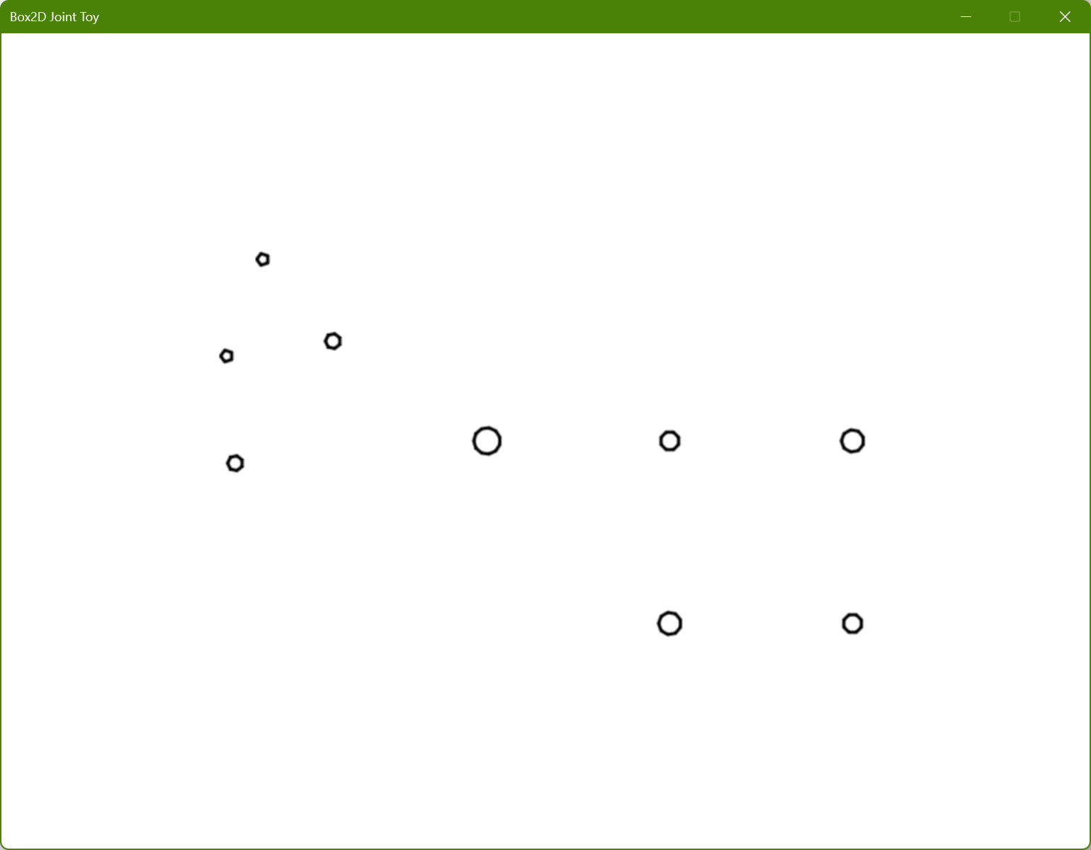
The Gear level is implemented in class CGear, which is derived from CLevel. It may come as a surprise that if you use F2 to draw the Physics World bodies, then you will see a collection of small non-overlapping circles as shown in Fig. 12, whereas in sprite mode you see gears of different size as shown in Fig. 2 happily rotating at the right speeds.
This brings us to what I call the First Law of Computer Graphics:
If it looks right, it is right.
and also what might be called the First Corollary of Computer Animation:
The things that you see on the screen don't actually interact - they are just drawn that way.
In this case it might look as if the gears mesh in such a way that the teeth of one gear pushed against the teeth of the next gear, but that really isn't so. All we need to do is make sure that the center of each gear is in the correct place, and that gears that should "contact" rotate at the correct relative speeds (and of course that the sprites have the correct number and shape of teeth for their size).
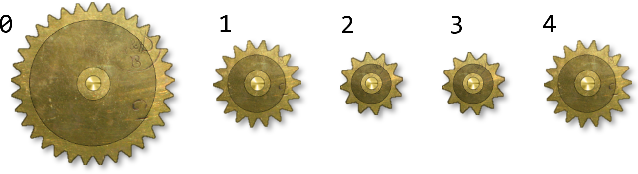
Consider the five round gears in Fig. 2. As seen in Fig. 13, we can number them 0 through 4. Note that gears 2 and 3 have the same diameter, but gears 0, 1, and differ from them and each other.
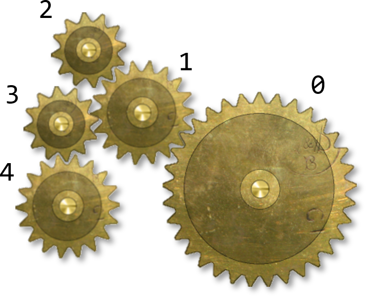
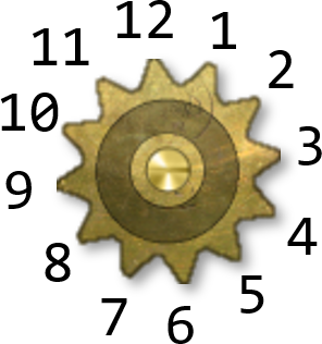
These are drawn as shown in Fig. 14 positioned and oriented so that their teeth appear to mesh together. As we animated the gears we just need to make sure that they stay that way. The largest, gear 0, will have a motor, and the others will rotate at the required speeds and directions. The relative speeds of rotation are proportional to the radii of the gears involved, which can be found by counting the teeth, as in Fig. 15.
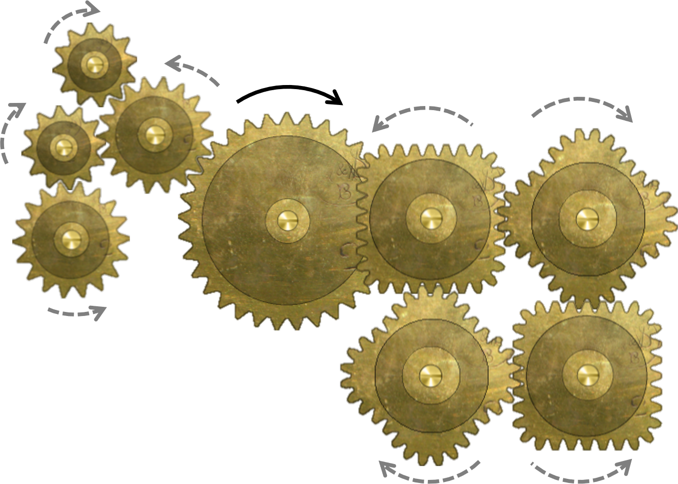
The relative directions of rotation flip from one gear to the next. For example, the largest gear in Fig. 16 is driven clockwise by a motor in a clockwise direction as indicated by the black arrows, while the other gears rotate in the directions indicated by the gray dotted arrows.
The code for the creation of the gears and their revolute joints is very similar to the code for the rotating fan in the Windmill level (see Section 5.3). Pointers to the revolute joints are stored in an std::vector of b2RevoluteJoint pointers CGear::m_stdJoint by the CGear constructor CGear::CGear. CGear::CreateGearJoint creates a gear joint that joins the revolute joints pointed to by m_stdJoint[i] and m_stdJoint[j], with gear ratio r, where the unsigned integers i, j, and the floating point value r are parameters. It does this by declaring a gear joint definition gd and filling in fields for the ratio, pointers to two revolute joints, and pointers to the corresponding two Box2D bodies. The gear joint is then created by calling
m_pPhysicsWorld->CreateJoint(&gd);
There is no need to save the joint pointer returned since it does not have any properties that we want to change, and it will be destroyed when the two revolute joints are destroyed.
Then, for example, the CGear constructor CGear::CGear makes the four following function calls for the gear joints joining gears 0 to 1, 2 to 2, 1 to 3, and 3 to 4. The third parameter in each case the ratio of the number of teeth in the second gear to the number of teeth in the first gear, noting that gear 0 has 33 teeth, gear 1 and 4 have 18 teeth, and gears 2 and 3 have 12 teeth.
CreateGearJoint(0, 1, 18.0f/33.0f);
CreateGearJoint(1, 2, 12.0f/18.0f);
CreateGearJoint(1, 3, 12.0f/18.0f);
CreateGearJoint(3, 4, 18.0f/12.0f);
The Nautilus Gear level is implemented in class CNautilusGear, which is derived from CLevel. A nautilus shell is the shell from the cephalopod family Nautilidae. A nautilus gear is made from a cross-section of a nautilus shell, two of which are shown in Fig. 17. The cross-section consists of a series of cells of increasing size that spiral out from a center point. In Fig. 17 the left-hand shell rotates about that point with constant angular velocity, while the right-hand shell rotates around its central point with angular velocity that increases and decreases over time so that the teeth appear to mesh. Remember that our task here is not to compute how the teeth mesh, but merely to draw the right-hand gear at an orientation that makes appear that it meshes with the left-hand gear.
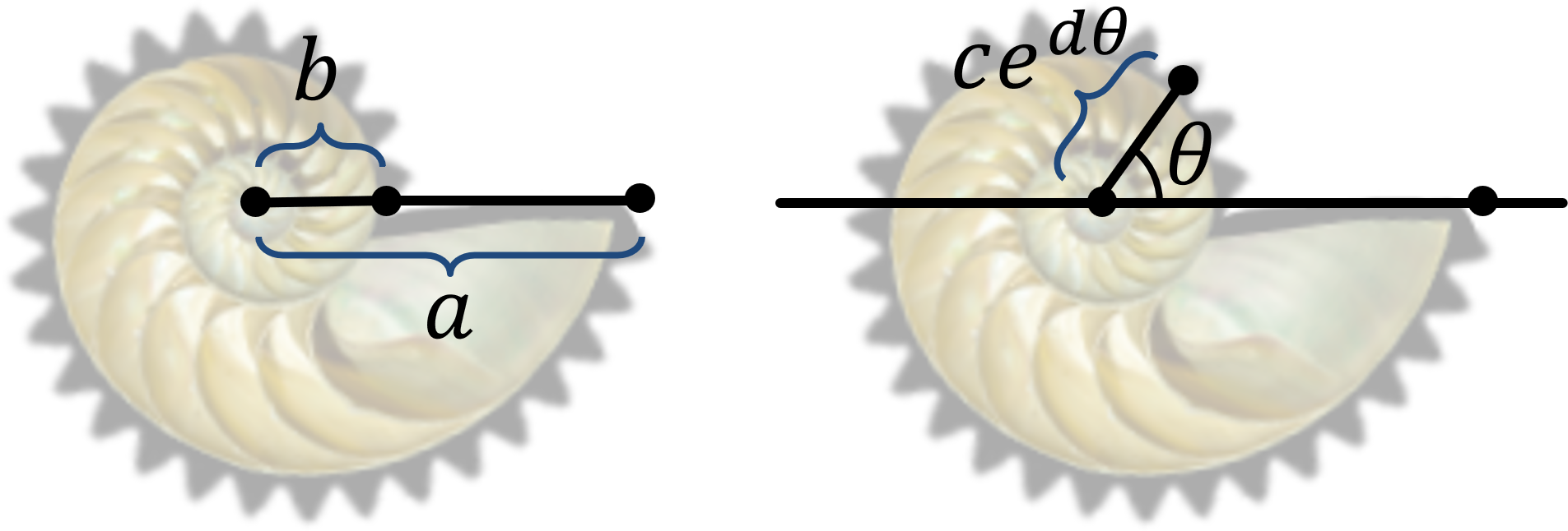
Since Box2D does not directly support nautilus gears, CNautilusGear will override CLevel::Move with a function CNautilusGear::Move that computes the orientation of the second gear from the orientation of the first gear. Recall that this function will be called once per animation frame from CGame::ProcessFrame. Up until now, the function call m_pLevel->Move() in CGame::ProcessFrame defaults to CLevel::Move, which does nothing. Before we write code for CNautilusGear::Move we will need to derive some mathematics about nautilus gears. Suppose we have a nautilus gear of maximum radius \(a\) and minimum radius \(b\), as shown in Fig. 18 (left). The radius of a nautilus gear at angle \(\theta\) measured counterclockwise from the positive \(x\)-axis (see Fig. 18, right) is \(ce^{d\theta}\) for some constants \(c, d\) that depend on the particular nautilus shell in question and \(e \approx 2.71828\) is the base of the natural logarithm. Since the radius at angle zero is \(b\), \(b = ce^0\), that is, \(c = b\). Since the radius at angle \(2 \pi\) is \(a\), \(a = be^{2 d\pi}\). That is, taking the natural logarithm of both sides, \(d = \ln (a/b)/2 \pi\). Examining our nautilus gear sprite in an image editor, we find that \(a=98\) and \(b=34\) pixels.
We thus begin our code for CNautilusGear::Move with \(\theta_0\), \(a\), \(b\), and \(d\). Variable theta0 holds \(\theta_0\), which is the opposite of the gear's orientation (from the gear's perspective, when it rotates through angle \(\theta\) it is as if the world has rotated through angle \(-\theta\)). CNautilusGear has constant member variables for \(a, b, d\).
const float a = 98.0f;
const float b = 34.0f;
const float d = 0.5f*logf(a/b)/b2_pi;
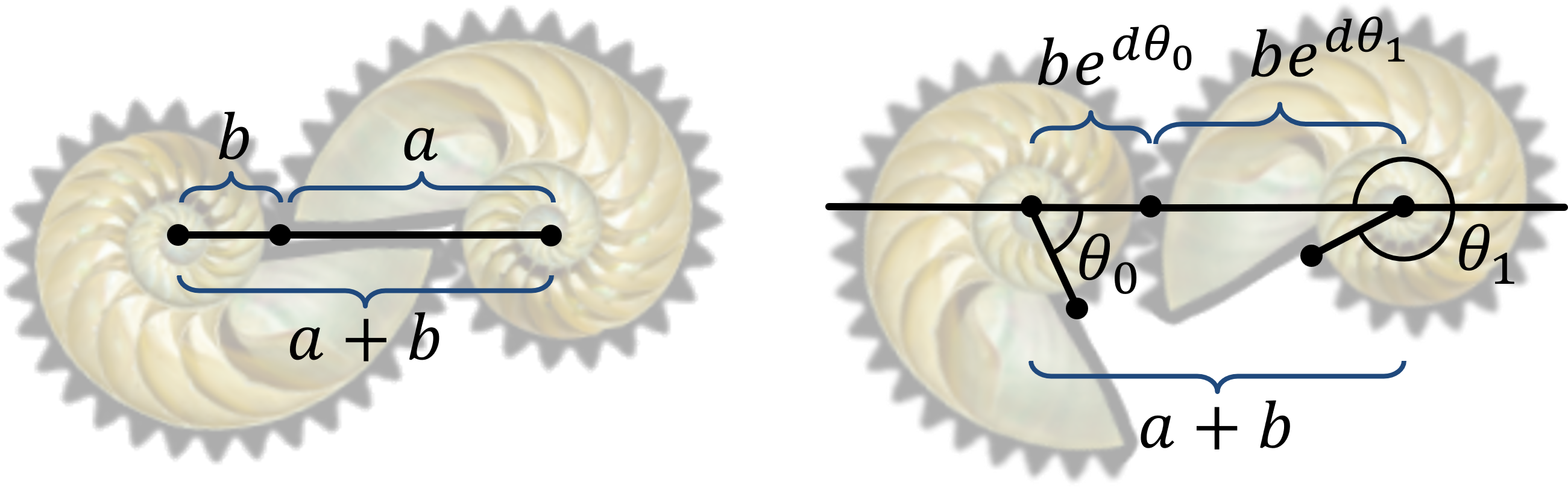
Since the fixed distance between the gear centers is \(a+b\) (Fig. 19, left), and \(be^{d\theta_0} + be^{d\theta_1}\) (Fig. 19, right), we can deduce that:
\[ be^{d\theta_0} + be^{d\theta_1} = a+b \]
which implies that, dividing both sides by \(b\) then subtracting \(e^{d\theta_1}\) from both sides:
\[ e^{d\theta_1} = a/b+1 - e^{d\theta_0} \]
and so, taking the natural logarithm of both sides and dividing by \(d\),
\[ \theta_1 = \ln(a/b + 1 - e^{d\theta_0})/d. \]
Since the right-hand gear starts out at an orientation of \(\pi\), its orientation is now \(\pi - \theta_1\). The code for CNautilusGear::Move is then:
void CNautilusGear::Move(){
  float theta0 = -m_stdObject[0]->GetBody()->GetAngle(); //left gear angle
  const float b2_2pi = 2.0f*b2_pi; //2 times pi in Physics World
  theta0 -= (UINT)floor(theta0/b2_2pi)*b2_2pi; //normalize theta0 to be in [0, 2pi]
  const float theta1 = logf(a/b + 1.0f - expf(d*theta0))/d; //angle for right gear

  b2Body* pBody = m_stdObject[1]->GetBody(); //body of right gear
  pBody->SetTransform(pBody->GetPosition(), b2_pi - theta1); //orient right gear
} //Move
The CNautilusGear constructor CNautilusGear::CNautilusGear calls CNautilusGear::CreateGear once for each gear to create it in the correct position and orientationas shown in Fig. 19, left. It then creates a revolute joint that connects the left gear to a null background, and enables its motor. This is similar to the CGear constructor CGear::CGear we saw in Section 5.3 except that it does not connect the nautilus gears with a Box2D gear joint. If CNautilusGear::Move were not called from CGame::ProcessFrame (for example, if you comment out the call to m_pLevel->Move()), then the left gear would rotate but the right gear would not.
The Rack-and-Pinion level is implemented in class CRackAndPinion, which is derived from CLevel. Its constructor CRackAndPinion::CRackAndPinion calls CRackAndPinion::CreateRack to create the rack (the horizontal part of Fig. 22), CRackAndPinion::CreatePinion to create the pinion, (the round gear in Fig. 22) and CRackAndPinion::CreateBase to create a null physics body for the background. It also creates a revolute joint for the pinion and stores a pointer to it in CRackAndPinion::m_pRevoluteJoint.
The horizontal motion of the rack is constrained by a prismatic joint that lets you set the direction of motion and the limits of travel. First we create a prismatic joint definition
b2PrismaticJointDef pjd;
A call to
pjd.Initialize(pBase, pRack, pRack->GetPosition(), b2Vec2(1.0f, 0.0f));
specifies pointers to the base body pBase and the rack pRack, the rack's initial position pRack->GetPosition(), and the unit direction vector pointing the positive X direction. Note that here and elsewhere it is important to create Box2D bodies in their initial positions and orientations, in contrast to graphics objects that can be creates at the origin and translated/rotated to their initial places. We then specify an upper and lower translation limit and enable limits.
pjd.lowerTranslation = -m_fLimit;
pjd.upperTranslation = m_fLimit;
pjd.enableLimit = true;
We can then create and save the prismatic joint.
m_pPrismaticJoint = (b2PrismaticJoint*)m_pPhysicsWorld->CreateJoint(&pjd);
A gear joint is used in order for the rack to move in synchrony with the pinion. W saw gear joints being used to connect revolute joints in \ref section5-2 "Section 5.2". Here a gear joint will be used to connect a revolute joint (for the pinion) with a prismatic joint (for the rack) using the pointersCRackAndPinion::m_pRevoluteJointandCRackAndPinion::m_pPrismaticJoint` created above. To do this we create a gear joint definition
b2GearJointDef gd;
set its ratio field to \(\pi\) divided by half the width of the rack sprite
gd.ratio = b2_pi/w2;
where we define
const float w = m_pRenderer->GetWidth(eSprite::Rack);
const float w2 = RW2PW(w)/2.0f;
and set its joint pointers
gd.joint1 = m_pRevoluteJoint;
gd.joint2 = m_pPrismaticJoint;
and provide pointers to the respective physics bodies
gd.bodyA = pPinion;
gd.bodyB = pRack;
We then go ahead and create the gear joint with a call to
m_pPhysicsWorld->CreateJoint(&gd);
There is no need to save the joint pointer so we don't.
Recall again that the pinion does not actually engage with and move the rack: the Box2D joints merely coordinate the position of the rack with the orientation of the pinion. The teeth are not present in the Box2D representation of the rack and pinion as shown in Fig. 23. It is up to us to create sprites with the teeth in the right places to create the illusion of a rack and pinion.
CRackAndPinion::Action is called from the keyboard handler in response to the space bar, overriding the default CLevel::Action. It merely reverses the direction of motion of the motor on the revolute joint by negating its motor speed.
void CRackAndPinion::Action(){
  m_pRevoluteJoint->SetMotorSpeed(-m_pRevoluteJoint->GetMotorSpeed());
} //Action
Although the prismatic joint's limits will prevent the rack from sliding too far to the left or right, we will need to add code to reverse the motor when either limit is reached. CRackAndPinion::Move is the perfect place to do this. It compares the prismatic joint position from m_pPrismaticJoint->GetJointTranslation() and the sign of the motor speed with the corresponding limit and negates the motor speed when the limit is reached.
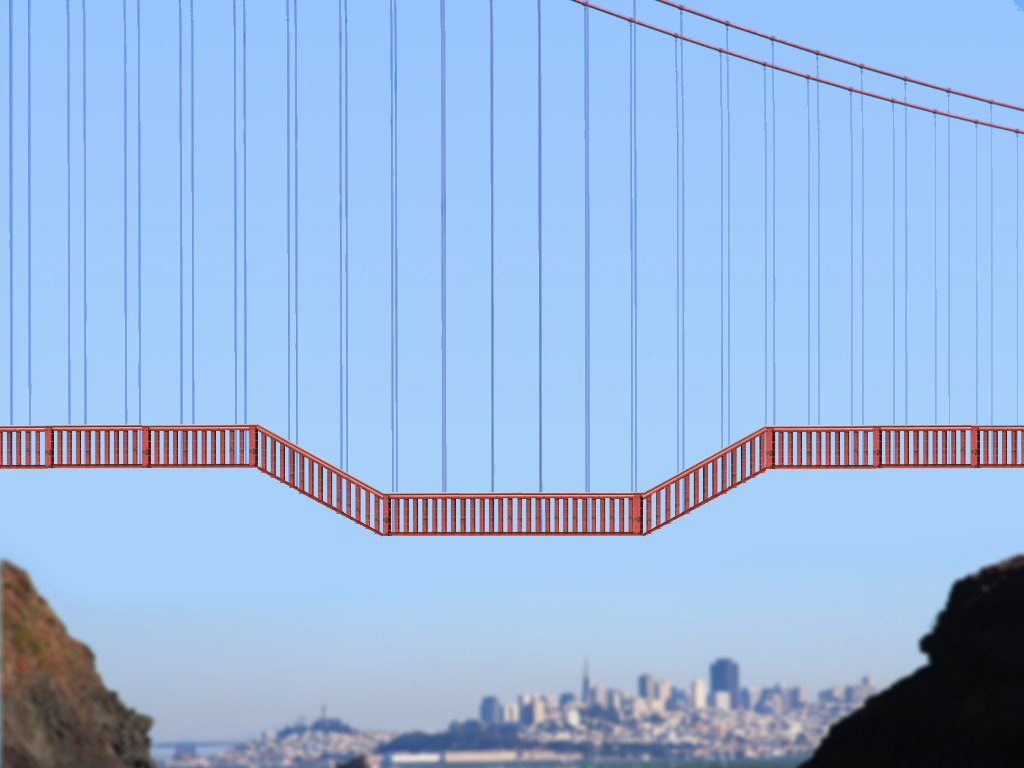
The Car and Bridge level is implemented in class CCarAndBridge, which is derived from CLevel. Most of what you see in the screenshot shown in Fig. 5 is baked into the background image shown in Fig. 24. The actual shapes in Box2D are shown in Fig. 25.
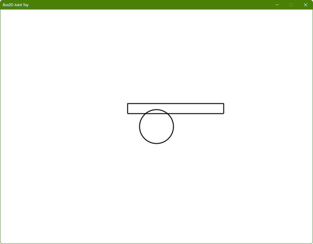
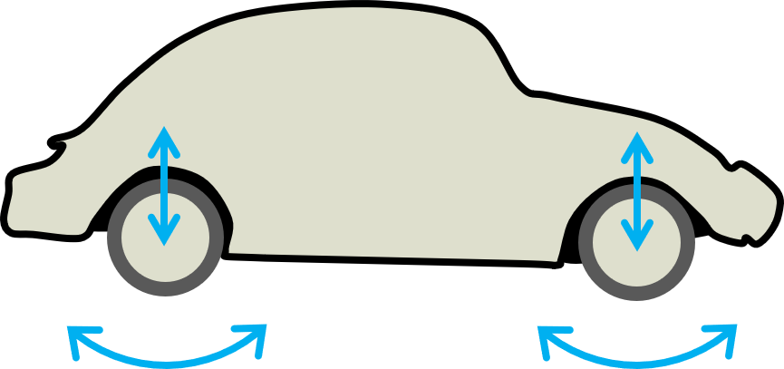
Much of the code for CCarAndBridge is similar to the code that we have seen in previous levels, including the use of CCarAndBridge::Move to reverse the car wheel motors when it nears the edge of the window. However, the wheels are not connected to the rest of the car using revolute joints. Instead we use wheel joints that allow the wheels to both rotate and move up and down as shown in Fig. 26.
This is done by creating an instance of b2WheelJointDef, setting and enabling its various motor-related fields, together with spring damping and stiffness values for the vertical motion. Finally, its collideConnected field is set to false so that Box2D will not respond to collisions between the wheels and the car body.
The Newton's Cradle level is implemented in class CNewtonsCradle, which is derived from CLevel. Its constructor CNewtonsCradle::CNewtonsCradle calls CNewtonsCradle::Create to create the balls and their joints. Fig 27 shows that each ball has a circle shape (compare to Fig. 6). CNewtonsCradle::Create calls CNewtonsCradle::CreateBall once for each ball in a for-loop, then calls CNewtonsCradle::CreateCradle to create the empty background. Finally CNewtonsCradle::Create creates the lines for the strings joining the balls to the cradle by calling CLevel::CreateLine once for each ball, then creates a distance joint by filling in an instance of b2DistanceJointDef with the positions of the ends of the strings and calling m_pPhysicsWorld->CreateJoint for each ball.
CNewtonsCradle::ResetBalls resets the balls to their initial positions with zero velocity. It does this by deleting the balls, lines, and joints and re-creating them by calling CNewtonsCradle::Create used above in the constructor. CNewtonsCradle::CreateBall deserves a little examination. Almost all of the code there should be familiar except for the last two lines. When these are executed the local variable pBody points to an instance of b2Body representing the newly created ball. The call to
pBody->SetAngularDamping(12.0f);
makes sure that the ball does not rotate about its connection point to its distance joint, which if you examine the code closely will be found at the top of the ball. Failure to set the angular damping to a high enough level will result in balls wobbling as shown in Fig. 28. Finally, the call to
pBody->SetLinearDamping(0.1f);
mimics the effect of the balls slowing down due to air friction.
The only interesting thing left is CNewtonsCradle::Action, which either stops the balls with a call to CNewtonsCradle::ResetBalls if they are moving or applies an impulse to the requisite number of them (see Section 4.6 for a reminder) by calling pBody->ApplyLinearImpulse to apply a horizontal impulse through the center of each ball body.
The Elephant Drop level is implemented in class CPulley, which is derived from CLevel. As shown in Fig. 9 (left), the level starts with an empty cradle connected to a heavy safe via two pulley wheels and a rope. Handily, Box2D includes a joint called b2b2PulleyJoint that connects a point on an instance of b2Body to another point on a second instance of b2Body. Here the first body will be the wooden cradle on the left side of Fig. 9 (left), and the second body will be the safe on the right side of Fig. 9 (left). The pulley joint is created in the CPulley constructor by filling in an instance of b2PulleyJointDef and using
m_pJoint = (b2PulleyJoint*)m_pPhysicsWorld->CreateJoint;
to save a pointer to the created joint in CPulley::m_pJoint.
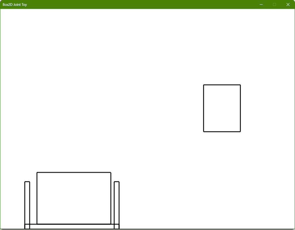
There will be three bodies with attached shapes (see Fig. 29), large rectangles for the elephant and the safe body respectively, and three narrow overlapping rectangles for the crate body. It is a little tedious to get the initial positions of everything lined up correctly, but you can read the rest of the code for yourself if you wish.
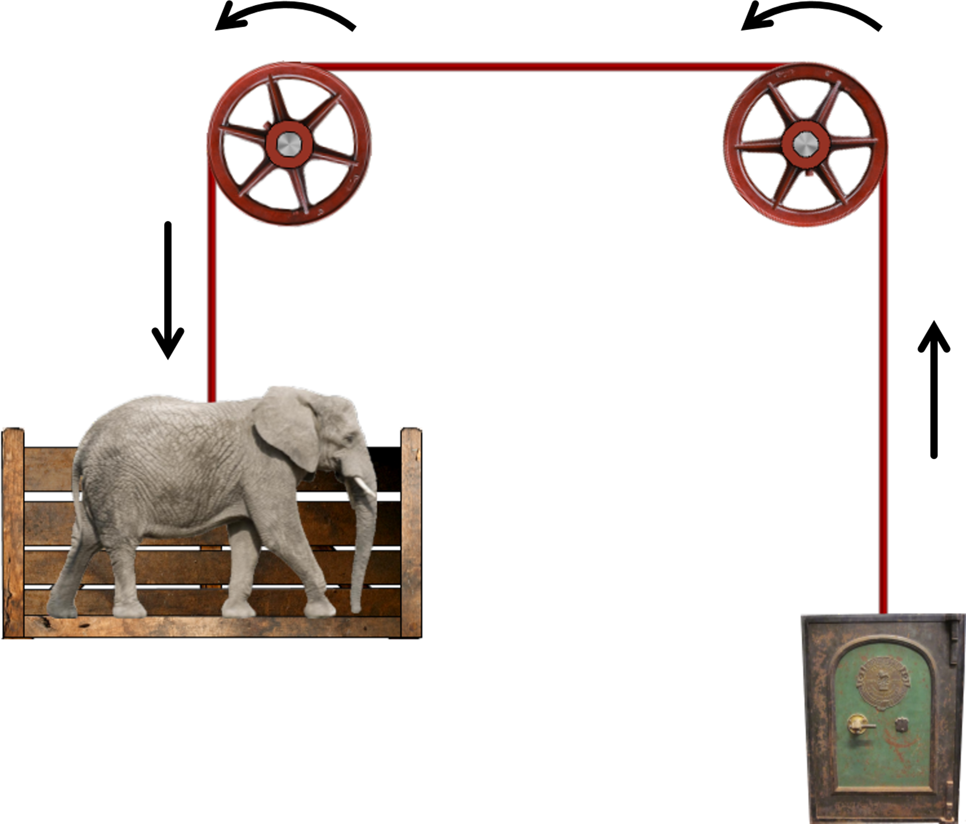
Unfortunately Box2D's pulley joint b2PulleyJoint does not have the concept of pulley wheels, just the positions of the ropes suspending the bodies attached to the joint. It is up to us to animate the pulley wheels in the correct directions as shown in Fig. 30. Fortunately b2PulleyJoint has a member function GetCurrentLengthA that returns the length of the left-hand portion of the rope. From this we can deduce how far each pulley wheel must rotate.
For example, if a call to the pulley joint's GetCurrentLengthA function reveals that the rope has moved distance \(d\) around the circumference of a pulley wheel of radius \(r\) (see Fig. 31) and the angle subtended by that segment is \(\theta\), then \(\theta = 2 \pi d/c\), where \(c= 2 \pi r\) is the circumference of the circle, and hence \(\theta = d/r\).
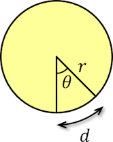
This calculation is carried out in CPulley::Move. The orientation of each pulley wheel is then set by calling their b2Body's SetTransform function with \(\theta\) as the orientation parameter and the the body's current position as the position parameter.
In the folder 8. Box2D Joint Toy in your copy of the sage-physics repository you will find a folder Problems which will contain some code to help you get started with the problems below.
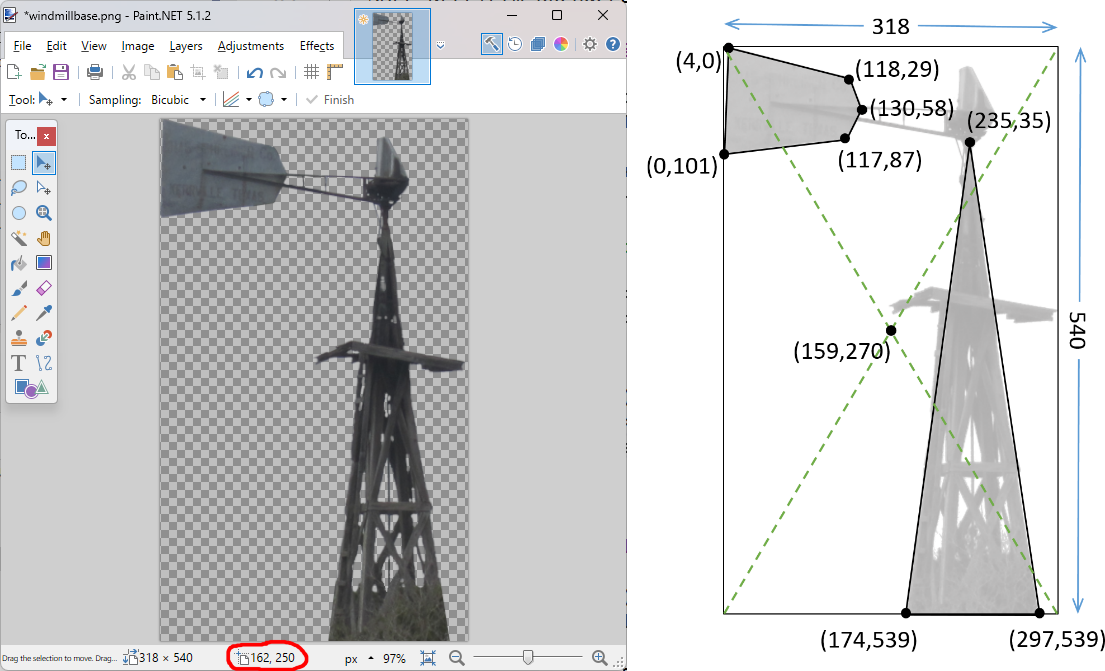
In the folder Windmill, which you will find in the Problems folder described in the introduction to Section 6 above, open Windmill.sln with Visual Studio. The key controls in Section 2 apply here too, except for the space bar which, instead of reversing the direction of the motor on the revolute joint, launches a collection of crates and balls using code borrowed from the Box2D Bouncy Things Toy.
CWindmill::CreateBase that adds shapes to the windmill base object so that the balls collide with the body of the windmill as shown in Fig. 91.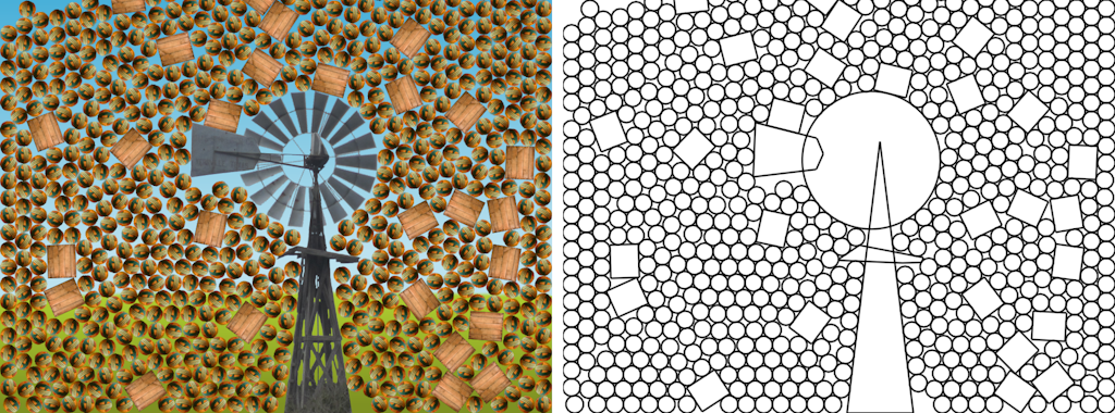
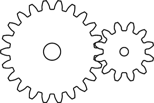
RemapPoints in Windmill.cpp that takes coordinates from the image and maps them to the correct equivalents for Box2D.In the folder Gears, which you will find in the Problems folder described in the introduction to Section 6 above, open Gear Toy.sln with Visual Studio. The first level of the Gear Toy corresponds to Problem 8.2.1 and displays two gears in their start positions and orientations as shown in Fig. 32. The second level of the Gear Toy corresponds to Problem 8.2.2 and displays two gears in their start positions and orientations as shown in Fig. 33. The third level of the Gear Toy corresponds to Problem 8.2.3 and displays two gears in their start positions and orientations are also as shown in Fig. 33. The key controls in Section 2 apply here too.
In the following problems, an external gear has teeth on the outside and an internal gear has teeth on the inside.
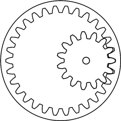
m_pJoint inherited from CLevel::m_pJoint. Your code must go into the CExternal constructor CExternal::CExternal in file Round.cpp. 
m_pJoint inherited from CLevel::m_pJoint. Your code must go into the CInternal constructor CInternal::CInternal in file Round.cpp. 
m_pJoint inherited from CLevel::m_pJoint. Your code must go into the CInternal2 constructor CInternal2::CInternal2 in file Round.cpp. 
In the folder Gears, which you will find in the Problems folder described in the introduction to Section 6 above, once again open Gear Toy.sln with Visual Studio. The fourth level of the Gear Toy corresponds to Problem 8.3.1 and displays two elliptical gears with the left gear driven by a motor as shown in Fig.35 and the right gear in its initial position. The fifth level of the Gear Toy corresponds to Problem 8.3.2 and displays two elliptical gears with the left gear driven by a motor as shown in Fig.35 and the right gear in its initial position. Before we start writing code we need some basic math facts about ellipses.
An ellipse is a shape that is formed as follows. Choose two distinct points called the foci (the singular of which is focus) and a distance \(d\). The perimeter of the ellipse is the set of all points \(p\) such that the sum of the two distances from \(p\) to the foci is equal to \(d\). In Fig. 37 (left), the point \(p\) is on the perimeter of the ellipse because \(d_0 + d_1 = d\). If we place the foci on a horizontal line, then the ellipse is symmetrical about horizontal and vertical lines through its center, and the foci are on the horizontal center line equidistant from the center, as we can see in Fig. 37 (right).
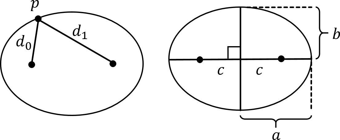
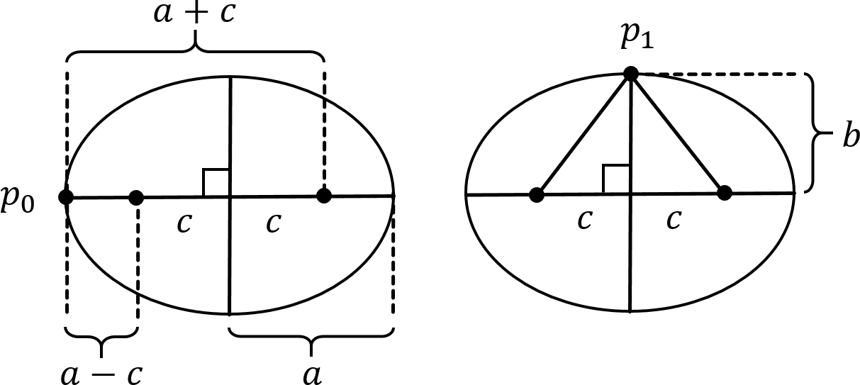
Let \(a\) be the length of the major (horizontal) axis, \(b\) be the length of the minor (vertical) axis, and \(c\) be the focal distance, that is, the distance from the center to either focus (see Fig. 37 (right)). The focal distance \(c\) is uniquely defined by the major and minor radii \(a\) and \(b\). That is, if we know \(a\) and \(b\), then we can calculate \(c\). This means that we can download an image of an elliptical gear from the internet, measure its height and width, and calculate \(c\) as follows.
Let \(p_0\) be a point at the end of the horizontal axis through the center of the ellipse. Then, as shown in Fig. 38 (left), the distance from \(p_0\) to the leftmost focus is \(a-c\) and the distance from \(p_0\) to the rightmost focus is \(a-c+2c=a+c\). The sum of the two distances is therefore \(2a\). Let \(p_1\) be a point at the end of the vertical axis through the center of the ellipse. Then, as shown in Fig. 38 (right) \(p_1\) is at distance \(\sqrt{c^2+b^2}\) from each focus, which means that the sum of the distances is \(2\sqrt{c^2+b^2}\). Since both \(p_0\) and \(p_1\) are on the perimeter of the ellipse, it must be the case that \(2\sqrt{c^2+b^2} = 2a\), that is, \(c = \sqrt{a^2 - b^2}\).
Let \(p = (x,y)\) be the coordinates of a point on an ellipse with major radius \(a\) and minor radius \(b\) centered at the origin. The sum of the distances from \(p\) to the two focal points is
\[ \sqrt{(x+c)^2 + y^2} + \sqrt{(x-c)^2 + y^2} = 2a. \]
That is,
\[ \sqrt{(x+c)^2 + y^2} = 2a - \sqrt{(x-c)^2 + y^2}. \]
Squaring both sides,
\[ \begin{align*} (x+c)^2 + y^2 &= \left( 2a - \sqrt{(x-c)^2 + y^2} \right)^2\\ x^2 + 2cx + c^2 + y^2 &= 4a^2 - 4a \sqrt{(x-c)^2 + y^2} + (x-c)^2 + y^2\\ 2cx &= 4a^2 - 4a \sqrt{(x-c)^2 + y^2} - 2cx\\ a^2 - cx &= a \sqrt{(x-c)^2 + y^2}. \end{align*} \]
Squaring both sides again,
\[ \begin{align*} (a^2 - cx)^2 &= a^2 ((x-c)^2 + y^2)\\ c^2x^2 + a^4 &= a^2x^2 + a^2c^2 + a^2y^2\\ a^4 - a^2c^2 &= a^2x^2 - c^2x^2 + a^2y^2\\ a^2 (a^2 - c^2) &= (a^2 - c^2)x^2 + a^2y^2 \end{align*} \]
Since \(c^2 = a^2 + b^2\), we can now substitute for \(b^2 = c^2 - a^2\).
\[ a^2b^2 = b^2 x^2 + a^2 y^2. \]
Dividing both sides by \(a^2b^2\),
\[ \frac{x^2}{a^2} + \frac{y^2}{b^2} = 1. \label{eq1}\tag{Equation 1} \]
\(\ref{eq1}\) is the equation for an ellipse in Cartesian coordinates.
Sometimes it is more useful to know the equation of an ellipse in polar coordinates. Let \(r\) be the length of a line at angle \(\theta\) counterclockwise from the long axis. This line ends at some point \(p=(r\cos \theta, r \sin\theta)\) on the ellipse. Therefore, by \(\ref{eq1}\),
\[ \frac{r^2\cos^2 \theta}{a^2} + \frac{r^2\sin^2 \theta}{b^2} = 1. \]
That is,
\[ r = \frac{ab}{\sqrt{b^2\cos^2 \theta + a^2 \sin^2 \theta}}. \label{eq2}\tag{Equation 2} \]
\(\ref{eq2}\) is the equation for an ellipse in polar coordinates.
As in Section 6.2, navigate to the Gears folder and open Gears.sln with Visual Studio. When you compile and run it, each level will correspond to a problem below and it should react to the key controls in Section 2 with the exception of the space bar, more of which later. The first level corresponds to Problem 8.3.1 and displays two gears in their start positions and orientations as shown in Fig. 32. The second level corresponds to Problem 8.3.2 and displays two gears in their start positions and orientations as shown in Fig. 37.
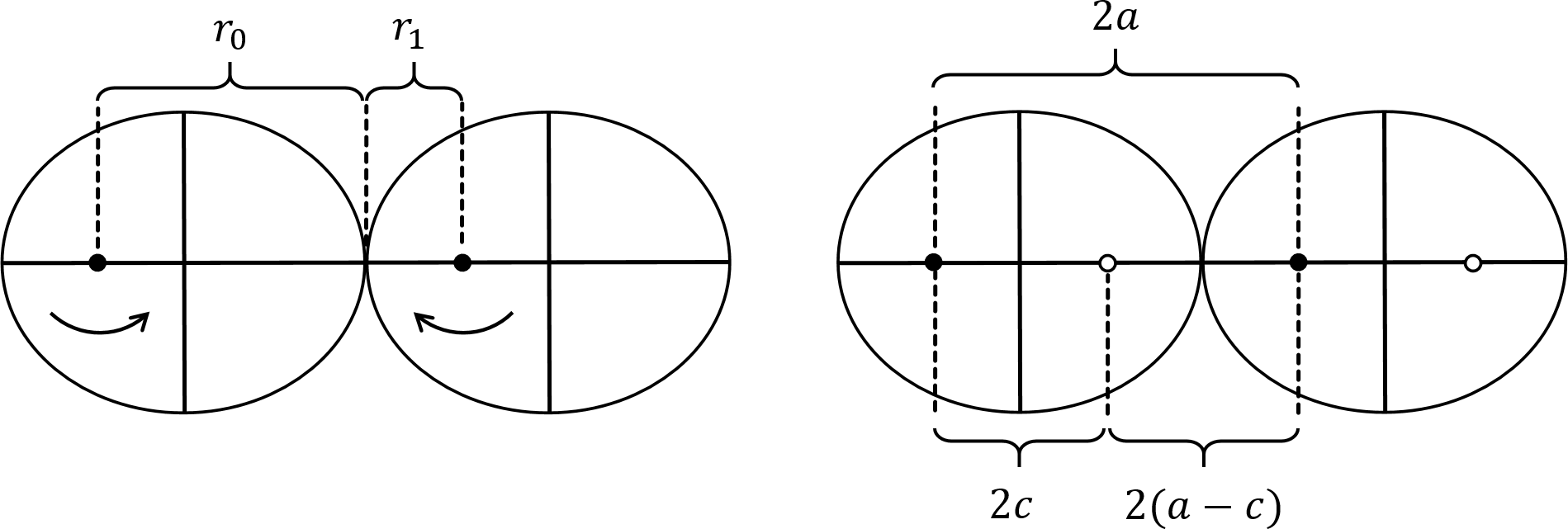
\[ r_0 = \frac{ab}{\sqrt{b^2 \cos^2 \theta_0 + a^2 \sin^2 \theta_0}}. \]
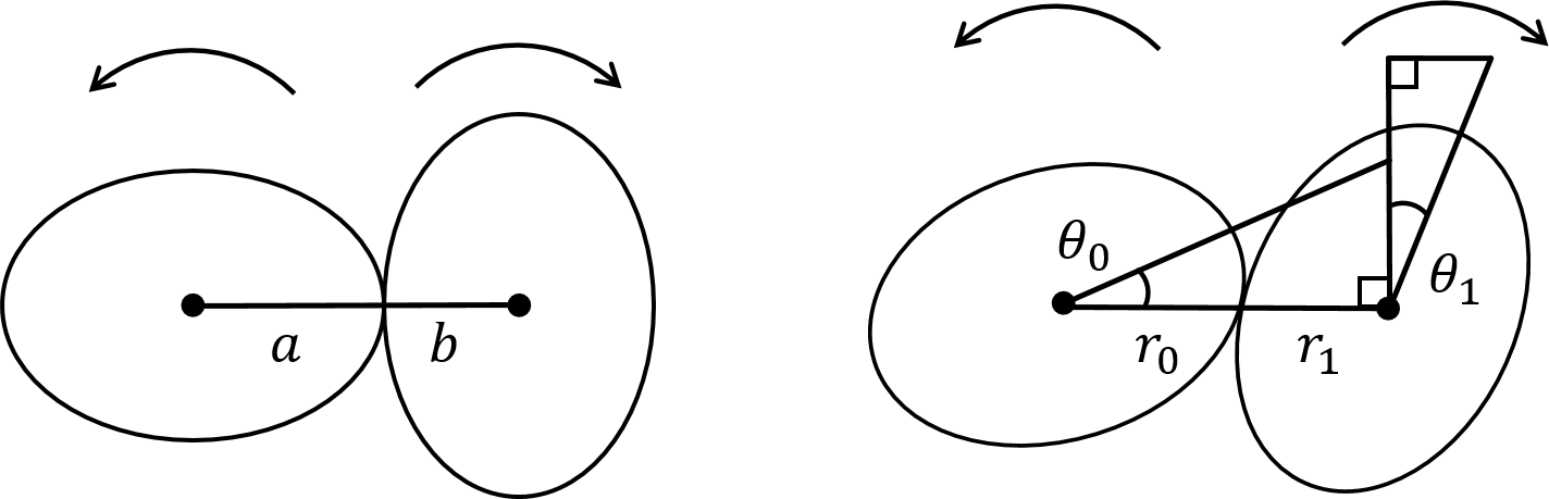
Since the initial position of the gears has one gear rotated by \(\pi/2\) with respect to the other (see Fig. 36, left), \(r_0+r_1=a+b\). Therefore, \(r_1 = a+b-r_0\).\[ r_1^2 = \frac{a^2b^2}{b^2 \cos^2 (\theta_1 + \pi/2) + a^2 \sin^2 (\theta_1 + \pi/2)}, \]
and therefore, inverting both sides and multiplying by \(ab\),\[ a^2 b^2/r_1^2 = b^2 \cos^2 (\theta_1 + \pi/2) + a^2 \sin^2 (\theta_1 + \pi/2) . \]
Since (by the Theorem of Pythagoras), \(\sin^2 (\theta_1 + \pi/2) = 1 - \cos^2 (\theta_1 + \pi/2)\), we Substitute for \(\sin^2 \theta_1\) in the above,\[ b^2 \cos^2 (\theta_1 + \pi/2)_1 + a^2 (1 - (\theta_1 + \pi/2)^2 \theta_1) = a^2 b^2/r_1^2. \]
Therefore,\[ \cos^2 (\theta_1 + \pi/2) = (a^2 b^2/r_1^2 - a^2)/(b^2 - a^2), \]
that is, since \(\cos (x + \pi/2) = \sin x\) for all angles \(x\),\[ \sin^2 \theta_1 = (a^2 b^2/r_1^2 - a^2)/(b^2 - a^2). \]
Therefore,\[ \theta_1 = \sin^{-1} ( \sqrt{a^2 - a^2 b^2/r_1^2}/f ) , \]
where \(f\) is the focal distance. We can therefore compute \(\theta_1\) from \(\theta_0\) and the major and minor radiuses of the elliptical gears \(a\) and \(b\) respectively as follows:const float CEllipticalGear2::ComputeTheta1(const float a, const float b, const float theta0){
const float x = b*cosf(theta0);
const float y = a*sinf(theta0);
const float r0 = a*b/(sqrtf(x*x + y*y));
const float r1 = a + b - r0;
const float f = sqrtf(a*a - b*b); //focal distance
const float d = a*b/r1;
return asinf(sqrt(a*a - d*d)/f);
} //ComputeTheta1
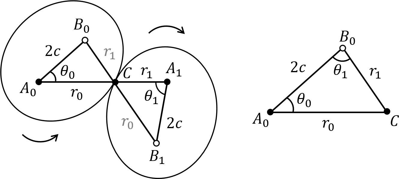
asinf returns a value in the first or second quadrant, whereas we want an angle that can be in any quadrant. The correct quadrant needs to be corrected in code or else the right gear sprite will jump from one orientation to another at multiples of \(\pi/2\).CEllipticalGear2::Move in file Elliptical.cpp to rotate the right gear meshed with the left gear as shown in Fig. 35. You may use function ComputeTheta1 as described above. \[ r_1^2 = r_0^2 + 4c^2 - 4cr_0 \cos \theta_0. \]
Recall that \(r_0+r_1 = 2a\) (see Fig. 37). Substituting for \(r_1 = 2a - r_0\) in the last equation,\[ (2a - r_0)^2 = r_0^2 + 4c^2 - 4c r_0 \cos \theta_0. \]
Solving for \(r_0\),\[ r_0 = \frac{c^2 - a^2}{c\cos \theta_0 - a}. \]
\[ r_0^2 = 4c^2 + r_1^2 - 4cr_1 \cos \theta_1. \]
Therefore, solving for \(\theta_1\),\[ \theta_1 = \cos^{-1} \left( \frac{4c^2 + r_1^2 -r_0^2}{4cr_1} \right). \]
theta1 from the orientation of the right gear theta0 and the ellipse radii a and b as follows. const float CEllipticalGear1::ComputeTheta1(const float a, const float b, const float theta0) const{
const float f = sqrtf(a*a - b*b); //focal distance
const float r0 = (f*f - a*a)/(f*cosf(theta0) - a);
const float r1 = 2*a - r0;
return acosf((4.0f*f*f + r1*r1 - r0*r0)/(4.0f*f*r1));
} //ComputeTheta1
acosf returns a value in the first or second quadrant, whereas we want an angle that can be in any quadrant. The correct quadrant needs to be corrected in code or else the right gear sprite will jump from one orientation to another at multiples of \(\pi/2\).CEllipticalGear1::Move in file Elliptical.cpp to rotate the right gear meshed with the left gear as shown in Fig. 37. Next, take a look at the Box2D Cannon Game.