 |
Wang Tiling
A Simple Wang Tiling Generator
|
 |
Wang Tiling
A Simple Wang Tiling Generator
|

The source code for this basic Wang tiling generator, written and maintained by Ian Parberry, is intended to be used by students to extend and modify while they are learning about Wang tiling. Wang tiling is a method for tiling the plane using only a small number of tiles, in this case 8 tiles, in such a way that large repeated patterns are minimized. See https://en.wikipedia.org/wiki/Wang_tile for more information.
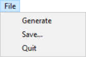
The controls consist of three drop-down menus, File, Tileset, and Help. The File menu lets you Generate a new Wang tiling, Save the current image, or Quit the application.
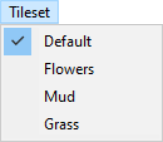
The Tileset menu lets you select from some hard-coded tile sets. A checkmark will appear next to the one that is currently displayed. See Fig. 1 for some examples.
The Help menu has two entries. The first is Display help which opens up this documentation in a browser.

The second entry in the Help menu is About, which displays the About dialog box.
It is assumed that the reader is familiar with the basics of Windows programming such as WinMain, the Window procedure, message passing, dialog boxes, and drop-down menus. Main.cpp contains the mandatory Windows functions wWinMain() and a Window procedure WndProc(), which share a single global variable static CMain* g_pMain. Most of the other gnarly Windows-specific code is hidden away in WindowsHelpers.cpp.
The two main classes are CMain, which encapsulates the main body of the code in the approved object-oriented fashion, and CWangTiler, which generates an array of tile indices for a pseudo-random Wang tiling over 8 tiles. CMain draws the Wang tiling to a Gdiplus::Bitmap using a selected tileset. This bitmap is drawn to the application window's client area only on receipt of a WM_PAINT message.
Pseudo-randomness is provided by an instance of std::default_random_engine seeded using the Windows MMIO function timeGetTime, which returns the number of milliseconds that have elapsed since Windows was last rebooted. This ensures that the probability of seeing the same Wang tiling twice is negligible.
The 8 tiles in the default tile set are depicted below in Fig. 2. The tiles are indexed 0 through 7 and the index is used as a file name, for example, tile 0 can be found in tiles\default\0.png. As we will see in the remainder of this section, the indexes have been chosen carefully so that their binary representation uniquely identifies the tile colors. This is the set of stochastic Wang tiles from
M.F. Cohen, J. Shade, S. Hiller, and O. Deussen, "Wang tiles for image and texture generation," ACM Transactions on Graphics, Vol. 22, No. 3, pp. 287-294, 2003.

The flower tiles in Fig. 1, second from left, were created by Ian Parberry by hand. The remaining tilesets were created using the quilting algorithm from:
A. A. Efros and W.T. Freeman, "Image quilting for texture synthesis and transfer", In Proceedings of the 28th Annual Conference on Computer Graphics and Interactive Techniques, pp. 341-346, 2001.
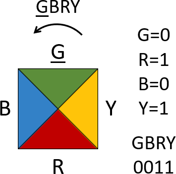
The default tile colors in Fig. 2 are green, blue, red, and yellow. A tile can be described by listing the first letter of the colors of each triangle counter-clockwise starting at the top. For example, the tile shown in Fig. 3 (which has index 1) can be described in alphabetic form as GBRY. Note that red and green can only appear at the top and bottom, and blue and yellow can only appear at the left and right (examine the tiles in Fig. 2). We can therefore assign green and blue bit 0, and red and yellow bit 1 without ambiguity. Each 4-letter tile description can then be replaced by the unique 4-bit number obtained by replacing each color with its corresponding bit, for example, GBRY can be replaced by 0011 (see Fig. 3).
The 4-bit representation is not ideal since 4 bits can describe 16 things whereas we have only 8 tiles. A compact 3-bit index can be obtained from a 4-bit number as follows. The first column of Table 1 below lists the 8 tiles in alphabetic form, with the corresponding 4-bit representation in the second column. Notice that the first two bits, which represent the top and left colors, respectively, have been indicated in red and have been copied to the third column of the table. Suppose the 4-bit representation of a tile is \(x_3x_2x_1x_0\), where \(x_i \in\{0,1\}\) for \(0 \leq i < 4\). Notice that \(x_3\) corresponds to the top color and \(x_1\) corresponds to the bottom color. The fourth column of Table 1 contains \(x_3 \oplus x_1\), where \(\oplus\) is the exclusive-or operator, which is 1 iff exactly one of its arguments is 1 and the other 0 and is implemented in C++ as operator^. Column four this contains the exclusive-or of the top and bottom colors of the tile. Notice that these parity bits are drawn in blue in Table 1. The 3-bit indexes listed in Column 5 of Table 1 are obtained by appending the blue parity bit from Column 4 to the pair of red bits representing the top and left colors from Column 3. Finally, the index in Column 6 is the integer whose binary representation is in Column 5.
| Colors | 4-bit | Top Left | Top \(\oplus\) Bottom | 3-bit Index | Index |
|---|---|---|---|---|---|
| GBGB | 0000 | 00 | 0 | 000 | 0 |
| GBRY | 0011 | 00 | 1 | 001 | 1 |
| GYGY | 0101 | 01 | 0 | 010 | 2 |
| GYRB | 0110 | 01 | 1 | 011 | 3 |
| RBRB | 1010 | 10 | 0 | 100 | 4 |
| RBGY | 1001 | 10 | 1 | 101 | 5 |
| RYRY | 1111 | 11 | 0 | 110 | 6 |
| RYGB | 1100 | 11 | 1 | 111 | 7 |
The process described in the previous section may be inverted, that is, the colors of the tile with a given 3-bit index can be found as follows. The first column of Table 2 below lists the 3-bit indices in numeric form with their binary representations in Column 2. Note that the left-most two bits, shown in red, are the colors of the top and left sides of the tile, and the rightmost bit (shown in blue) is the parity bit shown in Column 4 of Table 1, that is, the exclusive-or of the top and bottom colors. Suppose the 3-bit representation of a tile is \(y_2y_1y_0\), where \(y_i \in\{0,1\}\) for \(0 \leq i < 3\). Column 5 lists \(y_2 \oplus y_0\), which is the bottom color of the tile. These entries are draw in brown. Column 6 lists \(y_1 \oplus y_0\), which is the right color of the tile. These entries are draw in orange. The 4-bit representation of the tile can be found in Column 7. These consist of the red bits from Column 2 followed by the brown bit from Column 5, followed by the orange bit from Column 6. Column 8 lists the corresponding tiles in alphabetic form.
| Index | 3-bit Index | Top Left | Parity | Top \(\oplus\) Parity | Left \(\oplus\) Parity | 4-bit | Colors |
|---|---|---|---|---|---|---|---|
| 0 | 000 | 00 | 0 | 0 | 0 | 0000 | GBGB |
| 1 | 001 | 00 | 1 | 1 | 1 | 0011 | GBRY |
| 2 | 010 | 01 | 0 | 0 | 1 | 0101 | GYGY |
| 3 | 011 | 01 | 1 | 1 | 0 | 0110 | GYRB |
| 4 | 100 | 10 | 0 | 1 | 0 | 1010 | RBRB |
| 5 | 101 | 10 | 1 | 0 | 1 | 1001 | RBGY |
| 6 | 110 | 11 | 0 | 1 | 1 | 1111 | RYRY |
| 7 | 111 | 11 | 1 | 0 | 0 | 1100 | RYGB |
Function CWangTiler::Generate() tiles the grid in row-major order, that is, from left-to-right across each row, from the top row to the bottom. During each iteration a tile must be chosen matching the colors of the existing tiles above and to the left of the current grid position. That is, the top and left colors of the current tile are fixed by the bottom color of the tile above and the right color of the tile to the left. Notice, that the following property holds for the tile set in Fig. 2:
Key Fact 1: For every choice of top and left colors there are exactly two tiles that match.
Exactly which of the two candidate tiles is used can be chosen pseudo-randomly as shown in Fig. 4.
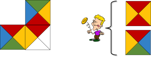
Key Fact 2: Of the two matching tiles in Key Fact 1, one will have its bottom and right colors equal to the top and left colors, respectively, and the other will have its bottom and right colors the opposite of the top and left colors, respectively.
For example, in Fig. 3 of the two candidate tiles on the right with top red and left yellow, the top one has identical bottom and right colors (bottom red and right yellow) while the bottom one has flipped bottom and right colors (bottom green and right blue). Key Fact 2 is the reason why we were able to get by with computing just one parity bit in Table 1 instead of two: if one of the bottom or right colors is flipped then they both are.
Suppose the tile above the current grid position has index \(y\), the tile to the left has index \(x\), and we need a matching tile with index \(z\). Let \(y_2y_1y_0\) be the binary representation of \(y\), that is, \(y = 4y_2+2y_1+y_0\). Similarly, let \(x_2x_1x_0\) be the binary representation of \(x\) and \(z_2z_1z_0\) be the binary representation of \(z\). Consider the choices for the tile in the current grid position, which is constrained by the colors of the tile above it and the tile to its left. Its top color \(z_2\) must equal the top tile's bottom color, which is \(y_2 \oplus y_0\). In code that would be (y&4)^(y&1)<<2 (noting that << has higher precedence than ^). Its left color \(z_1\) must equal the left tile's right color, which is \(x_1 \oplus x_0\). In code that would be (x&2)^(x&1)<<1. The remaining bit \(z_0\) can be chosen pseudo-randomly. This is implemented in CWangTiler::Match(). Refer back to Section 4.3 for more details.